ATSC 3.0 + 5G Broadcast on the Same RF: How the Knobs Actually Work
A practical, field-tested guide to time-multiplexing ATSC 3.0 with 5G Broadcast on a single RF channel. Written for broadcast engineers, system integrators and 3GPP-side colleagues who want a quick mental model before diving into A/321, A/322, or 3GPP TS 38.331. DigiCaster Scheduler (DCS) is used as the reference implementation throughout.
Why this is suddenly a question
Two things changed in 2024–2025. 5G Broadcast Rel-19 finalised the CAS-muting feature: the 5GB cell can be told to stay quiet on its Cell Acquisition Subframes (PSS/SSS/PBCH) for a programmed pattern of subframes per cycle, freeing the RF for someone else to transmit during those gaps. And ATSC 3.0 has always supported coexistence with non-3.0 signals on the same channel, by design — A/321 §6 lets a bootstrap announce, in a single 5-bit field, “the next ATSC frame won’t arrive sooner than X milliseconds.”
Put those two together and you have a credible path to a single 6 MHz (or 5 MHz, or 7/8 MHz) RF channel that carries both ATSC 3.0 and 5G Broadcast, time-sliced, with both receiver populations happy. Field trials are running now; the Las Vegas station is one of them.
The catch: getting the timing right requires three independent knobs to agree, and two of them live in different boxes operated by different teams. This brief lays out the knobs, what their valid values are, and how to set them in a real product.
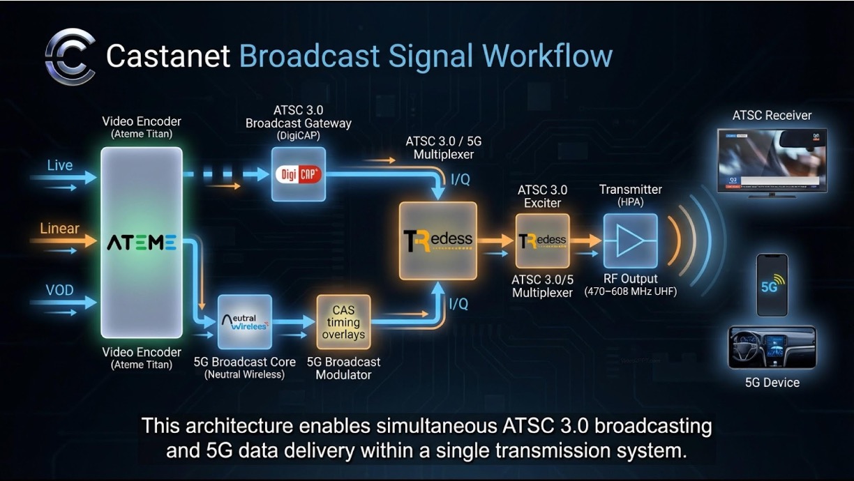
The picture
One TDM cycle, looking at the RF over time:

Three knobs, three owners:
| Knob | Where it lives | Owner | Quantum |
|---|---|---|---|
| CAS-muting cycle (active + inactive duration) | 5G Broadcast scheduler / 3GPP NR-MBS layer | 5GB operator | 1 ms (NR subframe) |
| ATSC 3.0 frame duration | ATSC scheduler (e.g. DCS) → carried in L1-Basic preamble | ATSC operator | 5 ms (when locked to time) |
min_time_to_next (next-frame promise) |
ATSC bootstrap (A/321) | ATSC operator | 50 / 100 / 200 / 500 / 1000 ms sliding |
The pattern is stable when CAS cycle ≈ ATSC frame interval, and min_time_to_next is the smallest legal value ≥ CAS cycle.
What the spec actually constrains
Knob 2 — ATSC frame duration
A/322 §9.2 puts the L1-Basic preamble in one of two modes via a single bit, L1B_frame_length_mode:
- Symbol-aligned (mode = 1, the common DCS factory default). Frame ends on whatever OFDM symbol boundary the FFT/GI/symbol-count math produces. You don’t pick the duration; you read it. A typical 6 MHz / 8K FFT / GI 1024 / 54-symbol subframe configuration produces a frame about 76.67 ms long. The spec carries
L1B_time_offset(16 bits) so the receiver can recover where the nearest millisecond boundary fell. - Time-aligned (mode = 0). Frame duration is chosen by the operator and signalled in
L1B_frame_length— a 10-bit field in 5 ms units, with legal range 10–1000 (so 50 ms to 5000 ms in 5 ms steps). The natural OFDM symbol math almost never lands on a 5-ms grid, so the leftover slack is redistributed across every non-preamble symbol’s guard interval viaL1B_excess_samples_per_symbol(13 bits). Receivers stay aligned because every symbol grew by the same number of samples.
For TDM with 5GB, you almost always want time-aligned mode. The 5 ms quantum is the smallest control you have; commit to it.
Knob 3 — min_time_to_next
A/321 §6, Table 6.3. Five bits, sliding-scale resolution, signalled in Bootstrap Symbol 1 of every ATSC frame. The semantics are:
bootstrap A promises that the next bootstrap (B) will arrive no earlier than T(X) ms and no later than T(X+1) ms, where X is the 5-bit value and T is the lookup table.
The table is dense at the low end (50 ms steps from index 0 to 6) and gets sparser as values grow. Around the values most relevant to 5GB CAS cycles:
  index 14  →  1100 ms   (window upper edge 1200)
  index 15  →  1200 ms   (window upper edge 1300)
  index 16  →  1300 ms   (window upper edge 1500)   ← granularity jumps to 200
  index 17  →  1500 ms
  ...
  index 31  →  RESERVED, MUST NOT be signalled
Two practical consequences:
- The spec lets you write any value, but the receiver-perceived window widens as you climb the scale. Past index 16 every step opens a 200 ms slack on the late side; past ~index 22 it’s 500 ms; etc. That slack is what absorbs cycle drift between the 1-ms-quantised 3GPP grid and the ATSC-side cadence.
- The scale has gaps in the range that matters most for 5GB Phase-2 patterns (1200 ↔ 1300 ↔ 1500). If your CAS cycle lands in a gap (e.g. 1280 ms) you cannot signal it exactly; you pick the nearest legal value above the cycle and accept that some emission windows will have no ATSC frame ready. Your transmitter fills those with plain OFDM to keep the AGC happy.
A four-step recipe
- Find the 5GB inactive window in milliseconds. From the 3GPP parametrisation (K_CAS, N_CAS, etc.), compute the two numbers: cycle period and inactive duration. Both are integer milliseconds.
- Set the ATSC frame to fit the inactive window. Round the inactive duration up to the nearest 5 ms. That value goes in
L1B_frame_length(in 5-ms units). - Pick
min_time_to_nextfrom A/321 Table 6.3 — the smallest table value that is strictly greater than the CAS cycle. If the cycle is 1280 ms, that’s index 16 (1300 ms). - Sanity-check the inequality.
min_time_to_next−L1B_frame_lengthmust be ≥ inactive window. (If it isn’t, the bootstrap promise overlaps your own current frame, which is meaningless.)
When min_time_to_next > CAS cycle, the emission rate exceeds the production rate and the gateway buffer drains; the system is stable and the “too few ATSC frames” condition shows up as occasional OFDM-filler windows. When min_time_to_next < CAS cycle, frames pile up and the transmitter restarts on overflow — typical failure mode is a periodic restart, on the order of tens of minutes, set by the buffer depth.
Configuring DigiCaster
DCS exposes the two ATSC-side knobs in two places under PHYSICAL SETTING → Preamble → L1 Basic Parameters:

The mapping back to the spec is one-for-one:
- Frame Length mode is
L1B_frame_length_mode(1 = Symbol, 0 = Time). - Frame Length [ms] is
L1B_frame_length × 5 ms. DCS rejects anything that isn’t a multiple of 5 — that’s the spec’s 10-bit-in-5-ms-units encoding showing through, not a DCS limitation. - Custom Frame Time = yes lets the bootstrap override the natural ATSC frame cadence with a chosen
min_time_to_nextvalue. - min_time_to_next is exactly the A/321 5-bit field, expressed in milliseconds; pick from Table 6.3.
The recipe in DCS terms: switch Frame Length mode to Time, type the inactive-window value (rounded up to a multiple of 5), set Custom Frame Time to yes, type the chosen min_time_to_next, click Apply.
A field example: the Las Vegas trial
- Channel: 6 MHz, single RF.
- Payloads: ATSC 3.0 ≈ 537 kbps; 5G Broadcast ≈ 4.45 Mbps on a 5 MHz inner bandwidth.
- 3GPP CAS-muting: K_CAS = 30, N_CAS = 8 → 1200 ms CAS-active + 80 ms inactive = 1280 ms cycle.
- ATSC frame length: symbol-aligned natural 76.67 ms; time-aligned recommended 80 ms (= 16 × 5 ms, smallest 5-ms multiple ≥ 76.67).
min_time_to_next: 1300 ms (A/321 index 16). Was 1200 ms initially, which produced 80 ms-per-cycle of buffer growth and a ~17-minute periodic transmitter restart; the bump to 1300 reversed the inequality and the system has been stable since.- Steady-state cost: the 20 ms / 1280 ms ≈ 1.5 % of cycles where no ATSC frame is queued get filled with plain OFDM by the exciter to maintain AGC. Sony chipset and EiTV ATSC 3.0 Analyzer Box receive cleanly throughout.
If Castanet 5G can shift K_CAS to make the CAS cycle land at exactly 1300 ms (e.g. 1220 ms active + 80 ms inactive), the OFDM-filler events disappear and the system runs in perfect lock-step. That is the long-term target.
Where the standards process landed
As of A/327:2026-04 (published 14 April 2026), this is no longer pending work. The amendment that started life as the S32 working draft A/327 Amendment — TDM of ATSC with Other Broadcasting Systems (2024-03-26) is now folded into the revised Recommended Practice itself. A/327 — Guidelines for the Physical Layer Protocol — is the authoritative reading for TDM coexistence; treat this brief as a practitioner-level walkthrough that points back to it, not as a substitute. Anything in here that disagrees with A/327:2026-04 should be assumed wrong, not the other way around.
Further reading
- ATSC A/321:2025-07 System Discovery and Signaling, §6, Table 6.3 —
min_time_to_next5-bit field and its sliding scale. - ATSC A/322:2025-07 Physical Layer Protocol, §9.2 — L1-Basic preamble syntax,
L1B_frame_length_mode, and the time-aligned vs. symbol-aligned branches. - ATSC A/327:2026-04 Guidelines for the Physical Layer Protocol (Recommended Practice, published 14 April 2026) — the authoritative reference for TDM of ATSC 3.0 with other broadcasting systems.
- 3GPP TS 38.331 (Rel-19) — CAS-muting parametrisation on the 5GB side.